10GHz Rainscatter
30 September 1995, GI8GJX to GM4JJJ, 220Km, IO74aq to IO86gb. Frequency 10,368.1 MHz Below is an audio spectrogram of the CW signal received over a non line of sight path from Northern Ireland to Scotland via a rain shower. Note the Doppler Spread of the signal.
Spectrogram (.gif)
Audio File (.wav)
Hear what it sounds like. (Very similar in sound to Auroral VHF backscattered signals)
Links to Other Microwave Radio Pages
There are some excellent sources of information on Amateur Microwave Radio on the Web. Here a just a few that I have found recently:-
Peter Day G3PHO's Microwave Pages
[Peter is the editor of the RSGB Microwave Newsletter.]
Dave - WA6CGR Microwave Pages
Excellent practical information on constructing high quality microwave equipment.
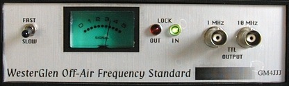
Notes on the Off-Air Frequency Standard - GM4JJJ
Corrections to 'Locking the Robin To Droitwich' - Practical Wireless Magazine.
Many people have tried to build this design and have got stuck when they found that there were many errors in the original published design. So far, Practical Wireless have not corrected any of the mistakes and the purpose of this article is to help constructors complete their project.
The original article which was published in two parts starting in Dec 95 Practical Wireless magazine was by Mike Rowe G8JVE.
The design gives 1 and 10MHz TTL outputs which are locked to the BBC Radio 4 signal on 198KHz.
This can be used as a High Stability Frequency Counter Timebase.
I recently received some very helpful notes from Richard G0RPH on his work on this design and I have now modified my previous notes to reflect his improvements.
Make sure that you read the corrections in Part 2 of the PW Article (Jan 96) before you do anything else.
Errors that P.W. have not published (yet)
Errors in the parts list which were in the most part easily sorted out from the circuit diagram:-
Download the corrected circuit diagram (pdf)
R5 = 1K2 R22 = 10K but now think this should be increased to 22K R25 = 2K2 R33 = 2K2 R37 = 100K R42 = 10K but now think this should be increased to 100K C25 = 10nF
Errors on the Badger PCB (and the Magazine PCB Artwork)
R22 - The end going to Pin 13 on IC2 should not be connected to the Groundplane of the PCB. ( It needs the Groundplane cleared around the hole).
The junction of C30 and D1 needs connected to the Groundplane. (Needs a wire link through one of the holes provided in the PCB).
Mistake on Both Circuit Diagram and PCB
There is a link missing between IC2 Pin 14 and the junction of R21 and C17. Without this link the 2KHz tuned filter works very poorly and there is insufficient gain to drive the meter circuit properly.
G0RPH has calculated that R22 should be changed from 10K to 22K.
Note on my prototype the 2KHz filter stage IC2b and IC2c went into self oscillation at 2KHz with these mods. Symptoms were a meter reading without IC1 fitted. To stop the stage oscillating I reduced R24 from 47K to 37K. (10K with 27K in series). You may have to experiment with R24 if you have similar problems. I found reducing the value of R24 reduced the gain and broadened the 2KHz filter slightly.
Another mistake on Circuit Diagram
Here is one that was not corrected in P.W. Jan 96 IC3 Pins 6 and 9 should be connected together. Note that the PCB artwork published in P.W. also misses this link, but that the Badger PCB is OK.
Some GM4JJJ Modifications
I have named my version the "Westerglen" as that is the BBC transmitter site that transmits 198KHz Radio 4 in Scotland. It is locked to a Rubidium Standard so should be 'good enough'.
Loop Time Constant
Although the circuit did seem to function now, I noticed that when listening to the 'note' of the 10MHz output on a Receiver, it sounded quite awful, as it was 'twittering' very badly.
The cure for this is to increase R42 from 10K to 100K. (Thanks G0RPH)
Comments
The text of the PW article is a bit confused about which pot is which.
R27 is for the meter sensitivity
R19 adjusts the centre frequency of the 2KHz IF filter.
Some other ideas from Richard G0RPH An even better (2KHz) IF response can be obtained by reducing L2 and increasing C10/12. I used 65mH with 100nF but even lower L would offer better stopband results. The lower XL gives higher Q with the fixed damping resistor (R16).
Disclaimers
The authors take no responsibility for any damage done from doing any of these mods.
Safety
I suggest that when testing the unit that you don't use the mains supply, instead use +13.8V DC into the external DC IN pin. ( I know it should be 18 volts, but 13.8V will work OK).
I wish you success with your project.
Alternatives
You may wish to also look at a modern GPS conditioned Unit like the Leo Bodnar.