GM4JJJ 144MHz XPOL Array Notes
Copyright © David Anderson GM4JJJ 1999
A practical guide to assembling an array of 4 Dual Polarity Antennas for 144 MHz EME - updated 20 September 1999
After many discussions with other fellow Moon Bouncers, I decided to build a dual polarity array to replace the previous 144 MHz EME antenna system which was destroyed in 100 MPH winds on 26th December 1998.
I purchased 4 off 2MXP20 Dual Polarity antennas which are manufactured in the USA by M^2 (M Squared). These 3 wavelength long antennas were the longest that I could accommodate at my location.
Because of the high cost of shipping to Europe, I did not purchase either the Hybrid Aluminium and Fibreglass H Frame or the rear T Brace Kit from M^2, instead I decided to manufacture my own from available materials.
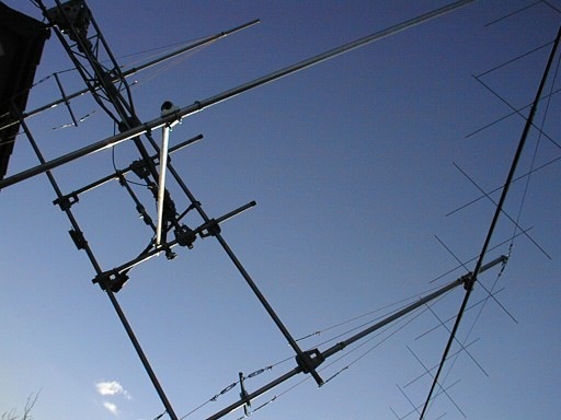
New array under construction - no feedlines, pre amp, relays or Driven element T Matches and Baluns fitted at this point.
H-Frame Design
Antenna Spacing is 144" in H-Plane and 146" in E-Plane. The H Frame uses a combination of Aluminium centre and Fibreglass ends for the vertical risers.
Dacron cord is used to brace the Fibreglass poles in 2 planes. Turnbuckles are used to tension the Dacron cord.
The feedlines leave the yagis at the rear and pass down the vertical aluminium braces and then along the horizontal braces to the power dividers which are at the centre of the H Frame. The Horizontal braces fitted in this manner add to the strength of the array. Thanks to Ed AL7EB for this idea.
Materials
I managed to get a local supplier of Pultruded GRP poles 32.1mm OD by 2.5mm wall thickness and lengths up to 9 metres from a local Kite Shop.
The H Frame horizontal and centre parts are 1.5" OD 10 SWG aluminium.
Vertical Risers Centres 1.5"OD aluminium 16 SWG 48" Long
Ends 1.5" OD 2.5mm wall Fibreglass 59" Long, jointed with 15" lengths of 2" OD thick wall aluminium scaffold tube.
The total length of the aluminium part is 60" and the Fibreglass poles have 56" exposed at each end.
The antennas on the Fibreglass are mounted symmetrically about the center spaced 144" apart.
I had to shim the 1.5" tubing to make it a tight fit in the 2" OD scaffold tube. I used glassfibre reinforced tape as a shim material. Bolts are used to hold the sleeves in place.
I found some very good parallel filament cord in my local ironmonger shop, it is sold as 'starter cord' for petrol chain saws and doesn't stretch, just like 'Dacron' and only 25 pence a metre
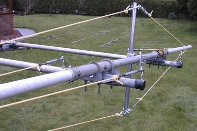
The hybrid Fibreglass and Aluminium H Frame with Dacron Bracing
Antenna Boom to Mast Clamp
The first problem I noticed was that I couldn't tighten the antenna mast clamps without crushing the Fibreglass tube. So I had to use a short (95mm) sleeve of 2" aluminium over the Fibreglass tube where the antenna clamps onto it. The sleeve is no larger than the mounting plate of the clamp so I hope that it will not affect the performance too much. The sleeve is pinned to the Fibreglass mast with 2 bolts.
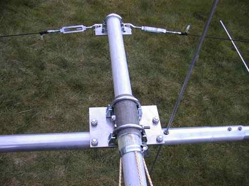
Reinforcement of Fibreglass with Aluminium where Boom to Mast Clamp is fitted
Also note the hose clamp holding the ends of the Dacron rope.
T-Brace
The JJJ 'T-Brace' is in two pieces. A vertical part joining the rear of the yagis and a horizontal part that goes from the centre of the vertical part to near the centre of my double H-Frame. The idea is that I will run the coax along these braces to the power dividers. I am very pleased with the added strength that the T-Brace idea has given the array.
Vertical part of the T Brace is 1" dia aluminium 12 feet long manufactured from 2 off 6 feet sections jointed with an outer sleeve and hose clips.
Horizontal is approx. 111" of 1.125" aluminium again made from 2 parts. It is jointed with an inner sleeve of 1" tube and held with metal screws.
The 1" vertical part of the T Brace intersects the rear of the yagis at the point M^2 recommends (16" from rear of boom). The Fibreglass mast mounting point is also at the M^2 point 116" from rear of boom.
2 Antennas mounted on frame with rear vertical braces and horizontal diagonal brace
Rear Brace of 1" aluminium and diagonal brace 1.125" aluminium
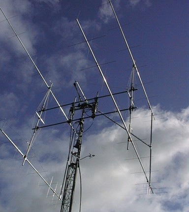
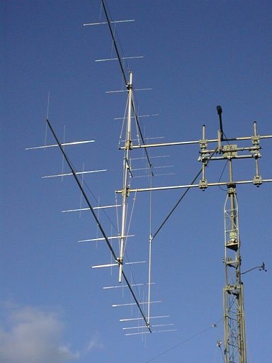
Array with feedlines complete, Note additional front bracing added to my H-Frame.
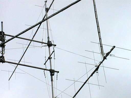
(Right) Additional Dacron Line and turnbuckle to rear of lower Yagi to reduce bending of Fibreglass Risers due to rear weight. Note also the tiedown rope added to lower crossboom (Left)
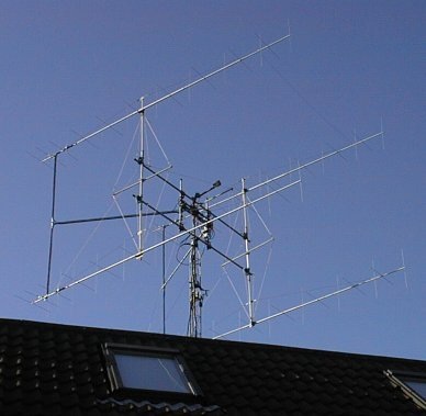
The completed array showing larger outriggers for bracing the vertical masts
Diary
Saturday: Cutting aluminium tubes for H frame and shim fiberglass tubing to fit the 2" sleeve sections with glass tape.
Sunday: Got some more hardware parts I needed, but no work done.
Monday: All day trying to locate more little things I needed, ended up driving about 60 miles during the day. Weather good
Tuesday: Drilled bolt holes in my jointing sleeves and got the Fibreglass risers fitted and shimmed properly. Weather good. Problem with next door's cat getting in my way all the time.
Wednesday: Fitted eye bolts and turnbuckles for bracing risers. Az Rotor re aligned. Salvaged old 4 way divider from previous array. I used a hose clip to hold the Dacron cords onto the Fibreglass poles. (4 cords bracing each pole.) Actually not real Dacron line, but very similar product designed as starter pull cord for chain saw motors.
Thursday: Seal my old power divider with hot melt wood glue. (tested glue stick for loss in microwave oven first). Elevation rotator adjust and grease knuckles. Mount Power dividers on stacking frame - quite a problem as they were different sizes and had to improvise with self adhesive rubber insulation as packing pieces to avoid crushing delicate M2 divider with clamps. Windy and bitterly cold. Build up 1 antenna boom to see how it looked.
Comments: I wish M^2 had numbered the boom parts, it takes quite a time to figure out which part is which as they look very similar. A simple number or colour would have made it easy! Weather forecast is rain... Still got the antennas to assemble (if I can get rid of that pesky cat)...
Phasing harnesses not started yet, I want to be sure of the exact lengths before I start cutting them. Preamp and relays have to be sorted out also. My array is mounted on a tilt over, crank up tower so I can work on it at ground level. The array should only just clear my house when it tilts over, so it takes quite a bit of planning to assemble it all. I am starting from the centre of the array out, because its difficult to reach the power dividers when the antennas are in place.
The Dacron stressed hybrid aluminium and Fibreglass risers appear to be pretty strong. I feel a lot happier about them now that I have the Dacron stress lines in place. I have left the Fibreglass sections full length and may cut it down to size when the antennas are mounted. Plan to use 144" vertical spacing.
T-Brace will use 1" aluminium tube for verticals and 1.125" for horizontal diagonal parts. Got some nice 1" clamps for jointing to yagis.
Friday: Today I assembled one yagi in the morning. Most time was spent sorting out which element was which (some are very close in size).Had to Drill out holes for U-Clips in booms.
Had to Reinforce Fibreglass mast where I clamp the antennas to the mast because the U bolts and saddles were going to crush the Fibreglass and I was really worried about doing real damage there.I opted for a sleeve of thick walled aluminium 95mm long (just long enough to go between the 2" U bolts on the existing clamp. Quite a bit of twisting is possible (torsion) in the Fibreglass poles even with my bracing lines.I am hoping that the T-Brace diagonals will take some of that twisting motion out however.
Another comment the Dacron line runs real close to the vertical elements and actually touches one of them - not much I can do there unless I put the support clamp on the other side of the vertical mast. Hopefully next antenna will be quicker to assemble!
Saturday: Built up yagi number 2. Fitted to frame. Built T Brace. Vertical is 2 * 6' of 1" Al joined by split sleeve and hose clamps.Horiz is 2* 1.125" sections joined by 1" insert. 200mm with sheet metal screws. Horizontal total length 111".Did not use saddle clamp for lower dacron support because of fear of crushing tube.
Sunday: Built up other T-frame.
Monday: Built last 2 yagis and mounted on tower with T-Brace. Moved lower yagi guy clamps up to 20"
Tuesday: Straightened up array. Took old HF wire antennas down. Measured required phasing harness lengths - 19' should do.
Wednesday: Made 4 phasing lines for vertical elements 5.50m longWestlake 103. 145.187MHz = 3.25 WL dip.
Thurday: Looked into preamp designs.
Friday: Parts missing for some antennas! Checked VSWR of one antenna both planes - OK. Used FT290R and Welz SWR meter. Unwanted cross coupling seems to be very low.Cable length OK for Vertical, needs to be shortened for Horizontal. (By 20"* Vel Factor of cable).
Hit my first real problem today. I have some parts missing from my antennas! :-( They only supplied 2 'shorting blocks' instead of 4 for each antenna! - Well actually they got it right for one antenna, but the other 3 boxes only had 2 shorting blocks each.
Had hoped to be up and running this weekend! - Thought it was going too well :-) My Phasing lines are 18 feet long for the Vertical elements and I am going to make them shorter for the Horizontal, both for physical reasons and for easier phasing later. (I will make them 20" x 0.85 shorter (the cable velocity factor is approx. 0.85).
Saturday: Phasing lines for Horiz made. Westlake 103 cable 157.085MHz dip (3.25 WL). 5.084m long.Checked VSWR of Vertical array ; excellent across band.
Sunday: Fit remainder of phasing lines. Fit front brace for H Frame.
Monday: Looking for coaxial relays in my junk box, lost one?
Tuesday: Photos of relays emailed for identification.
Saturday: Put relay and preamp on H Frame.
Tuesday: M2 missing parts arrived. Refitted one Dacron line turnbuckle that had undone.Crimped more N Type cables.24", 32", 36", 2m.
Thursday: Put more coax pieces on array.
Saturday: Waxoyl fittings on array. Fit remainder of cables to array. Spray yagis with Halfords clear laquer (Acrylic). Adjust elevation.Retension fibreglass turnbuckles.Straighten H Frame up and tighten clamps.Tune Up into array 900w/50 w reflected.Thunder & Lightning.
Sunday: Sun Noise tests 6dB. Front end of RX conv blown when changing Polarisation while on TX by mistake. I notice that the local intermod is much stronger on Vertical than Horizontal. (This is intermod at a TX site not at my RX, so no filtering here can cure it). Tropo signals show the expected large signal strength changes if I switch to opposite polarisation
Sunday: Water on elements causing leakage.Eagle power divider leakage.One Horiz phasing line leakage at soldered connector.SWR of H & V measured OK at antennas.One Mast Bracket slightly overtightened.
Spent today checking SWR of individual yagis again and found one coax cable with moisture in it, of course it was the -second- coax connector that I unsoldered that fixed it! Then found that one of my Power Dividers is bad. The good news is that the SWR of the yagis has not moved a bit since I sprayed them with clear lacquer. It looks like a replacement Power Divider will cure the different match between H & V that I currently have.
A week later... still no power divider from M^2. Looking into making a divider out of Heliax as a temporary measure (9H1PA design ideas). My RX converter has a new BF981 RF stage fitted and is working again.
Consensus on Moon-Net is that I should have used a hardened steel stub mast rather than the 2" heavy duty alloy scaffold pole.
Sunday: Fitted two more Dacron Lines and turnbuckles to the array. The lines go from the rear of the lower yagis to to topmost metal part of the H-Frame. This modification has much reduced the bending of the vertical fibreglass risers. I am sure once I use stronger Dacron here it will completely eliminate it.
Fitted two ropes to the lower crossboom to tie the array down during high winds. Fitted 18" elastic shock cords to ends of these ropes. Array much steadier in gusty winds now.
Saturday: Constructed Power divider from Andrew 7/8" Heliax and connectors/ T pieces. Checked VSWR of divider with loads on each port - flat across band. Checked power on each port was equal. Fitted this divider in place of the old water logged divider on the tower. Checked insulation with DMM then SWR - excellent across the band. Adjusted tension on various ropes to make array as square as possible. Cut the excess Fibreglass from below the two lower yagis. Sprayed Acrylic clear coating on Fibreglass poles for UV protection and water proofing.
Checked SWR on Horizontal plane in shack, now reflected power does not show on the Bird wattmeter - much better (Had about 50watts reflected before). Listened on bottom end of band and heard RU1AA on Vertical and later when I was a bit more organised I heard Peter SM2CEW Calling CQ , again stronger on vertical, so gave him a call and he came straight back with a 529 report. No other stations heard. Played around with the amplifier tuning to see what the difference is between Horizontal and Vertical. Although SWR appears the same on either, the loading on the PA is different, which causes a problem because my screen current trip can go off very easily if the loading is different. May have to try some stub on one polarity to make the match the same on Horizontal and vertical. This will not be easy with the polarity relay up at the mast head.
Discussions with Leif SM5BSZ about different loading on PA between Vertical and Horizontal: His suggestion is to change the length of the feedline on one polarity to equalise the PHASE of the Forward and Reflected power on Vertical and Horizontal. I calculate that I need to lengthen my existing Horizontal coax link between the polarity relay and power divider by about 4" to get the total cable length the same on Horizontal and vertical. I could check this in the shack by adding a 4" piece on output of PA and see if things change as expected. This has come about because I made the phasing lines different lengths between Horizontal and Vertical. The SWR (amplitude) is pretty much the same on Vertical and horizontal, however because of different line legths the phase is different.
Noticed that when elevated the upper pair of yagis splay out very slightly. I may use some dacron cord between the front of those beams to try and stop this from happening. It may just be a case of some slight realignment is required.
Now ... Tidy up the shack, it is like a disaster area after all the recent work!
Friday: Antennas replace dacron on rear of lower yagis. Straighten up array including making sure that all individual yagis are in the same plane. Measure coax between splitters and relays. Added a light piece of Dacron between fronts of the upper two yagis to stop them splaying..
T98 expedition worked on EME random. A real struggle to hear. Suspected my RX preamp not up to par or something...
Saturday: Noticed that local beacons seem very weak and not moving S Meter at all! - Found that the BF981 in RX converter was not amplifying at all. replaced and beacons back up in strength. Big improvement to EME signals now. Discussions with Steve K0XP concluded that BF981 is being destroyed by RF coming down the RX line on transmit, possibly when accidentally switching polarity c/o relay while still on transmit. Measured power at input to RX converter while on Transmit : -6dBm on Vertical and -10dBm on Horizontal.
Skeds after RX converter repaired were all complete. Benefit of V/H switching apparent on sked with Bill AB3D who was worked TX V and RX H.
Sunday: Put a protection relay in ahead of my RX converter to isolate it more while on transmit. Converter RF stage not powered during transmit and relay switches input to 50 ohms load during transmit.
Saturday: Decided to revisit the Dacron bracing on the vertical risers. Previously I used a jubilee hose clip to hold the Dacron onto the fibreglass mast, this had not been a big success because the Dacron could be pulled loose when tensioning up with the turnbuckles. I used some metal 'mending stip' which has holes in it. The strips were bent slighly and attached with a hose clip and a self tapping metal screw into the fibreglass. Used D Shackles through one of the holes in the strip to attach the Dacron. I also lengthened the metal outriggers for the vertical mast bracing. This has solved the problem of the bending of the fibreglass completely.
I lengthened the coax segment between the Horiz power divider and the Polarity relay, by an amount calculated to equalise the Horiz and Vert coax lengths. This has cured the different loading I was experiencing on the PA and the Preamp when switching polarisation.
Phasing Lines
My lines ended up 5.5m (18 feet) for the Vertical which worked out at 3.25 wavelengths at 145.187MHz (that's where I got the null).That makes my cable's vel factor = 0.82. My other lines for the Horizontal were made shorter by 20" (the boom distance between H & V driven elements ) times the vel factor, so ended up at length 5.084m and were 3.25 wavelengths at 157.085MHz. Used a Signal Generator and RF milliVoltmeter to get the nulls when I trimmed the cables. Used T piece and fitted one connector to cable and trimmed other end for a null on meter. How to match lengths
Frequently Asked Questions
> Where can I buy Westflex 103 coax cable?
Westflex 103 cable is available only from:
W.H Westlake
West Park
Clawton
Holsworthy
Devon
EX22 6QN
Tel +44 (0)1409 253758
>Did you have any problem getting a good impedance match?
No, I checked each antenna after setting the shorting blocks to the M2 dimension and the SWR was 1:1. Seemed good across whole of the range 144 to 146 as well. I then tried all 4 vertical antennas with the M2 splitter and again SWR was excellent. This was with the antennas pointing straight up and reflectors only a couple of feet off the ground. A quick check on one Horizontal yagi also gave very good SWR. I also checked to see if there was any significant degree of coupling from H to V and it was very low indeed (Put power meter and dummy load on Horiz and fed Vertical elements.
> Have you details of your 7/8" Heliax 4 way power divider?
I built this in a hurry because one of my original metal tube divider was leaking water. It has worked so well I will probably stay with it.
Note unless you can get inexpensive surplus connectors for the Heliax it is not going to be cost effective to try this.
You will need:
4 off N type male plug connector for the 7/8" Heliax. I used surplus ones made by Spinner.
3 off N type T adaptors (sockets) - I only had 2 T pieces with all female sockets, so I had to use one with a male plug as the middle one. There is a small difference in the length of this style of T adaptor.
I had to measure the effective lengths of the mated connectors and T pieces allowing a velocity factor of 0.985 for those parts. The Heliax has a velocity factor of 0.89. I ended up cutting the Heliax to 350mm lengths and fitting the N type connectors (2 required).
The completed divider consists of two quarter wave lengths of 7/8" Heliax with a T piece in the middle and a T piece at both ends. Very simple to make and waterproof. Wrap all connections with self amalgamating tape when installed.
I tested the divider with four 50ohm loads and the SWR was low and flat across the 144-146MHz band. The power division was equal on all 4 ports. I guess that proves my calculations were correct.
9H1PA has made dividers out of 7/8" Heliax also. His method is different. He uses a continuous half wave length of Heliax and fits normal type N sockets as the connections. Requires carefull drilling and soldering and probably is slightly lower loss. I opted for the easy way because I had the connectors and was in a hurry to be QRV. I cannot measure the loss of my dividers, but I can not see any difference in performance between my 7/8" Heliax divider and the M^2 divider that I use on the other (vertical) half of the array.
>Have you found an easy way to center the elements when assembling the yagis?
Yes, I found the easiest way was to center the elements by measuring them as per my chart and then put a mark on the elements either side of the shoulder washers (button insulator) with a permanent marker, so if they do slip when fitting the shaft retainers, I could see where they should be. As M^2 suggested I used a pair of locking grips clamped up lightly against the opposite insulator while pushing the first shaft retainer into place.
Since M^2 didn't supply a handy chart of the dimensions when each element is centered, I have produced my own: Dimension is from shoulder face of Button Insulator to the tip of element in mm
|
|
|
|
|
|
|
|
|
|
|
|
|
|
|
|
|
|
|
|
|
|
|
|
|
|
|
|
|
|
|
|
|
|
|
|
|
|
|
|
|
|
|
|
>Do you have any other tips?
Yes, Making up Phasing cables is one of the most labour intensive activities in this project.
I used WESTFLEX 103 cable which is the same as Aircom. Purchase the Special Easy to Fit N Plugs from Westlake, they have the correct size of centre pin to accept the 2.7mm inner conductor of W103 and this saves a lot of time. These Special N Types are soldered on in a similar fashion to the regular PL259 plugs. You can get them off again if you need to, but it ain't too easy!
I also got some surplus Amphenol N Types that required a crimp tool to fit. Unfortunately the centre pin was designed for 2.5mm conductor, so it meant filing the inner conductor down to fit. The crimp tool set was not too expensive from Maplin Electronics and can be used with all sizes of coax cables. You cannot reuse the crimp plugs if you ever need to get them off for any reason.
Check all of your cables for isolation and continuity before and after soldering/crimping. I bought a secondhand 'Megger' Insulation tester which is extremely useful for testing cables for good isolation.
Do not over tighten any of the mast to boom clamps - including the mounting plate to mast clamps because the aluminium mounting plate will distort. (I did this accidentally with one yagi)
Get the Strongest Fibreglass tubing that you can. I find that the 2.5mm wall thickness is not as stiff as I would like it to be and it has a slight bend due to the rear weight of the array and phasing harness. Bracing of the Fibreglass is definitely required in a windy location.
You can never have enough Cable Ties and Self Amalgamating tape!
Future Plans
For winter storms I plan to make a trestle to tilt the tower onto and then tie the array down.
Upgrade pre amp to Power GaAsFET with cavity input and 5 pole filtering on output. I have a real problem with a strong out of band carrier mixing with other out of band signals and it is not clear if the mixing is at my mixer or the transmit site (Several Km away but line of site).
Logic switching for polarity relay (So it can only be changed while not on TX)
Power is now increased (8877 PA).
Thanks to AL7EB VE7BQH K6MYC 9H1PA SM2CEW SM7SJR F/G8MBI SM5BSZ VE3KH GW3YDX W7GJ W3SZ and all on Moon-Net for their help and advice.
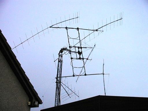
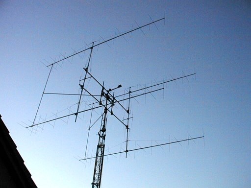
Previous 4 * 17 ele CueDee 3.6 WL array after 100 MPH storm in December 1998
Tower Head Unit, Azimuth Rotator output flange and mast clamps, thrust bearing and yagis were damaged.
Note that the aluminium stub mast is still straight! - The headunit buckled and the flange rotator clamps fractured.
This array also had a wideband Discone and a 24 ele 432MHz beam inside it. The loops are excess Heliax in the phasing harness!
UK to American English
Fibreglass =Fiberglass
Aluminium = Aluminum
Centre = Center
Metre = Meter
Polarisation = Polarization
Car = Automobile